915MHz LoRa Wireless Deer Notification System
Join me on my unique journey from novice hunter to tech-savvy innovator. What started as quiet moments in the deer blind with my dad evolved into a quest for a game-changing hunting tool. Frustrated by missed opportunities in the field, I explored wireless communication technologies and discovered LoRa, a powerful and free-to-use system. With its long-range capabilities, I set out to design an advanced alert system to detect nearby deer movement and relay it seamlessly to my blind. Dive into the blend of tradition and technology that has transformed the way I hunt.
Background
I’ve been deer hunting with my dad since I was about 18 years old. At first, it was only every few years that I would go out with him. However, in recent years, my interest has grown and now I find myself taking the entire opening week of hunting season off from work to go hang out in the woods.
Over the past two years, I’ve seen lots of deer while sitting in the woods and have been able to harvest two deer—one in each year. Last year, I missed the chance to get a shot off at a few deer because I didn’t have enough time to draw my weapon before the deer was swiftly out of sight.
While sitting there waiting for activity to present itself, there is abundant time to think and ponder about a myriad of things. Last season, after missing the chance at an 8-pointer, I found myself thinking about ways in which I could be notified of nearby deer activity. A simple wireless transmitter that could send messages to a receiving unit in my deer blind was the initial thought.
Initial Research
After doing some research on wireless communications, I found that, in order to achieve longer range, a lower carrier frequency is desirable. After looking into the frequencies available to the public, I found the LoRa technology which operates in the 915MHz range for the US. Based on my initial research, I found the specs of LoRa allowed for up to 20km range with line-of-sight. In my deer blind, the longest range I would need was about 300 yards, but with a few trees in between.
Requirements
After finding out that the range I was seeking was definitely possible with free-to-the-public frequencies, I started deciding on design criteria for the receiver unit that would handle the messages coming from the transmitter devices. Here is the list of features I wanted:
- 4 LED indicators to show where messages were coming from
- Audible bird chirp to audibly, and discretely, alert me of nearby activity
- Volume control
- Audio enable switch
- USB-C charger
- Remote LEDs for spatial awareness of where activity is coming from
- SMA antenna connector
- On/Off switch
Prototyping – Sparkfun ProRF
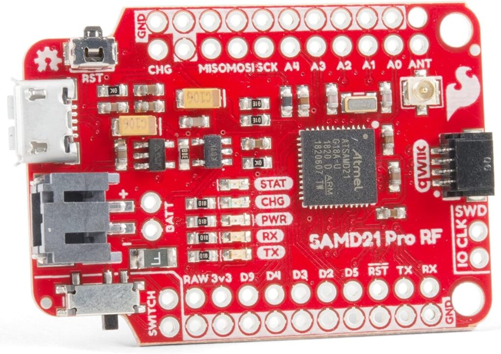
I started researching different LoRa boards to get started with testing. At first, I purchased a pair of the Sparkfun Pro RF boards which appeared to be a good choice given its built-in lithium ion charger, sleep modes, on-board uFL connector, and decent number of I/O pins.
After making some small modifications to the example codes provided by Sparkfun, I had a transmitter which could transmit messages with an incrementing counter and a receiver to receive the messages. I quickly volunteered my girlfriend to help me test out the range at a nearby park. With the transmitter stationary, I took the receiver hooked up to my tablet and started walking while carefully monitoring the received messages to make sure none were missed. I made it out to about 300 yards before I got my first missed message. I had been walking with the receiver in front of me, so I stopped and faced the transmitter. The intermittent messages appeared to stop. I then continued to walk further, making sure to keep the antenna up above my head. At about 430 yards, I was well into the woods and with a pretty decent elevation variation between me and the transmitter. The transmitter was lower in elevation, however there was about a 50 foot tall hill in between the transmitter and receiver. It was at this point that I was receiving about 50% of the messages being transmitted, so I concluded the testing there. Definitely much further than I needed for my application.
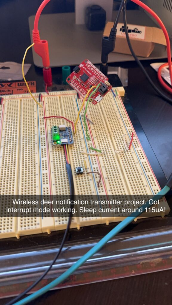
At that point, I started figuring out what size and how many batteries I would need to ensure the transmitter would last an entire hunting season. The transmitter would need to operate for about about 1 month in freezing temperatures without needing to be recharged. The current draw of the board was about 60mA while idle. There was a substantial increase in current when transmitting messages, about 120mA, but only for about 100ms. This seemed excessive, given the datasheet stated an idle current of a few hundred µA. I tested out the sleep modes offered by the MPU on the board and was able to get it down to about 30mA, but this was still orders of magnitude larger than expected. At this point I was stumped. After reading more about the board, I found a note from the manufacturer that there was a mistake on this revision of the board where VDD was tied to GND. After finding this, I was able to cut this trace on the board and get the sleep mode current down to about 115µA. Success! In idle mode, this could theoretically run on a single 3500mAh lithium ion cell for about 4 years—much longer than I needed. Granted, the average current draw would be higher than the sleep mode current due to the current spikes when transmitting messages, but even at 1mA, this battery could power the board for nearly 5 months.
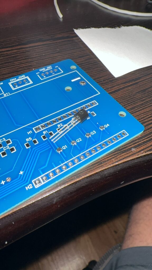
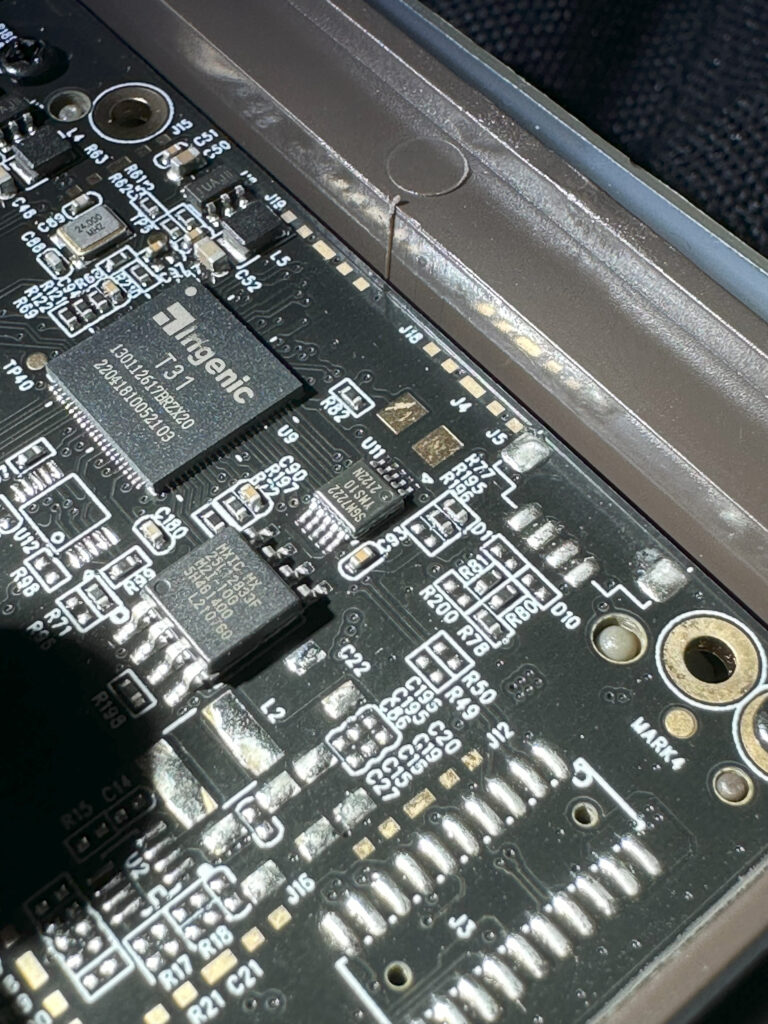
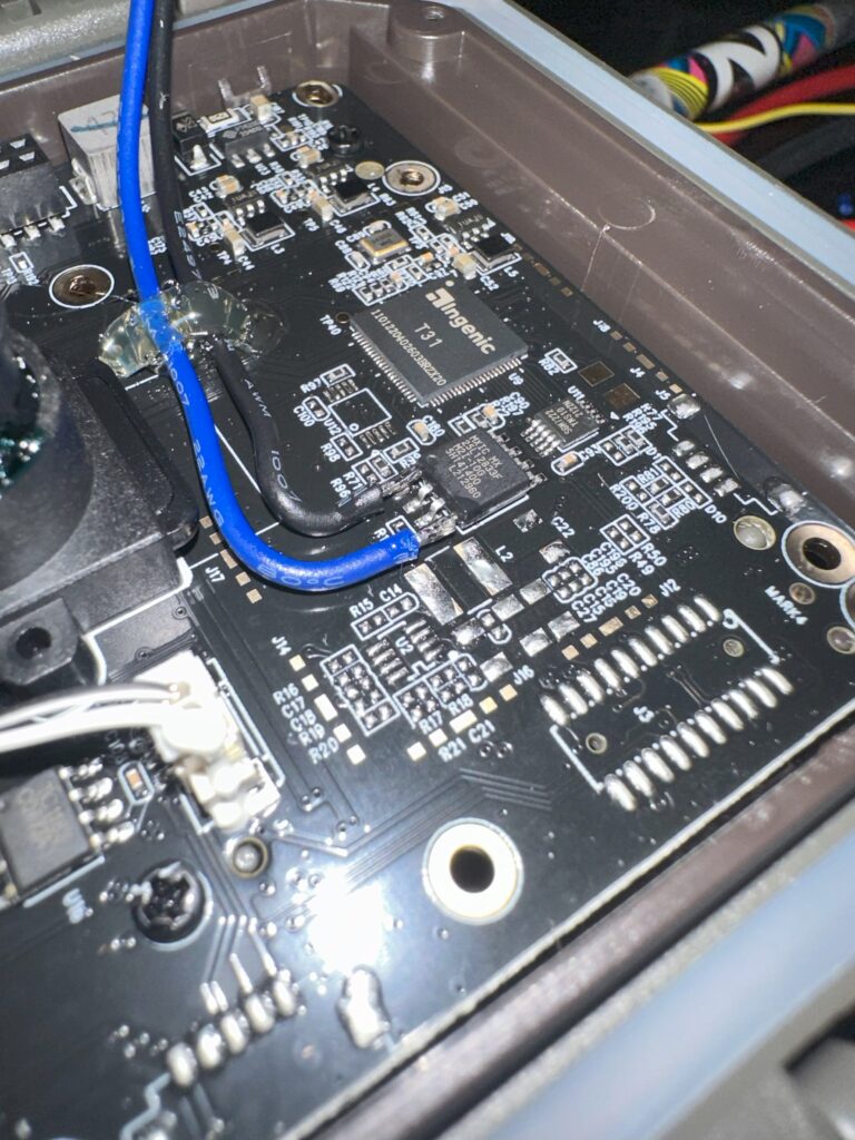
The next step was to open up a game camera I’ve used before and had good luck with. I figured using an off-the-shelf game camera would serve two main purposes. The first being I knew I could get reliable triggers of deer with minimal false triggering when no deer were present. The second upside was that I could have more pictures of deer to admire later. The camera I used was a Meidase P60 trail camera. Upon opening up the camera, I noticed there were 2 PIR sensors to detect motion.
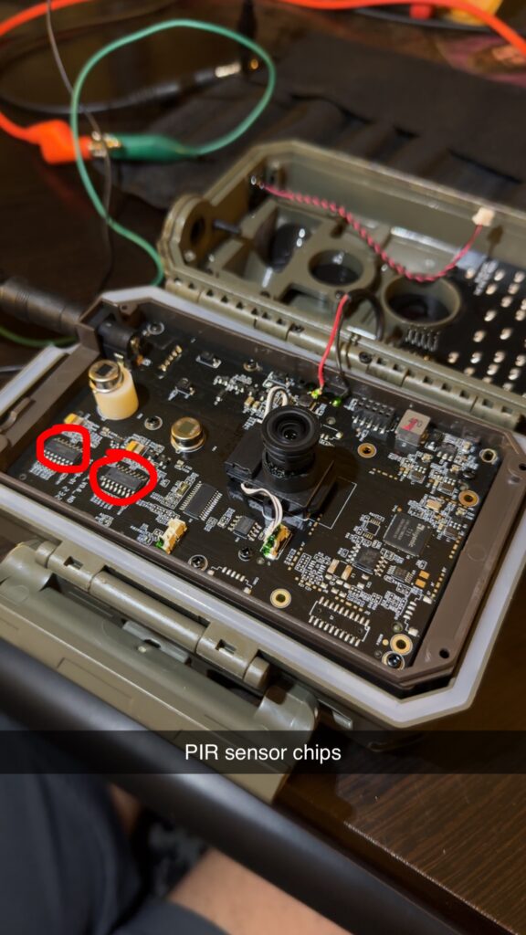
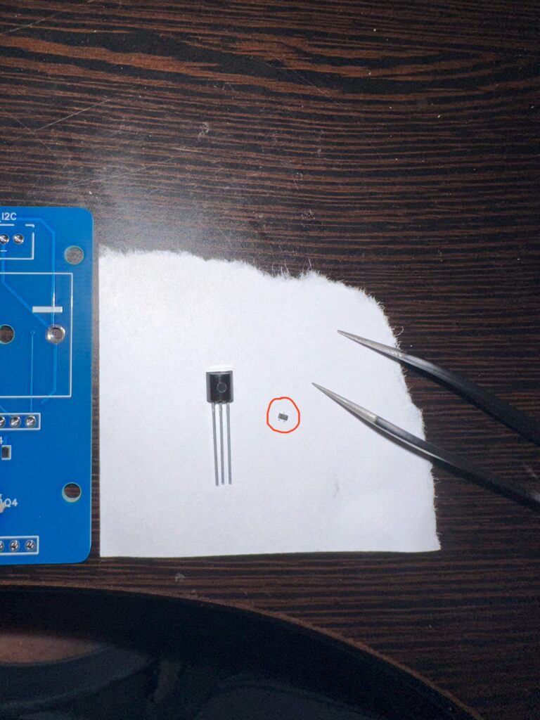
By checking the output pins from these chips, I thought at first I could simply use these as my trigger source. However, after further testing it was evident that there was some pre-processing of these signals going on before the camera would actually take an image. This made sense because there are sensitivity settings on the camera that can be adjusted. After looking over the other ICs on the board, I found a CMOS flash memory chip.
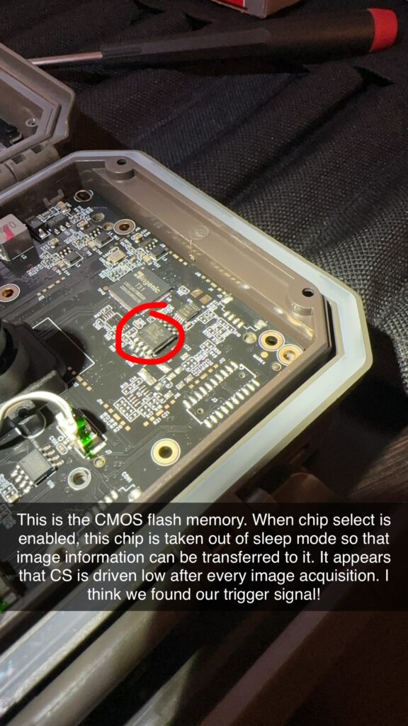
After reviewing the datasheet and probing the IC for a bit, I found there was a chip select (CS) pin on the IC that was only active when acquiring an image and when changing settings on the camera’s menu. Since I would not be changing settings on the cameras while in my deer blind, I decided this would work well enough for a trigger signal. An added benefit of using the CS pin for a trigger signal is that it was already 3.3V which works well for most microcontrollers. After connecting the CS pin to one of the Pro RF’s I/O pins, I was quickly able to verify that this was able to give me a reliable trigger signal to transmit messages when an image was captured.
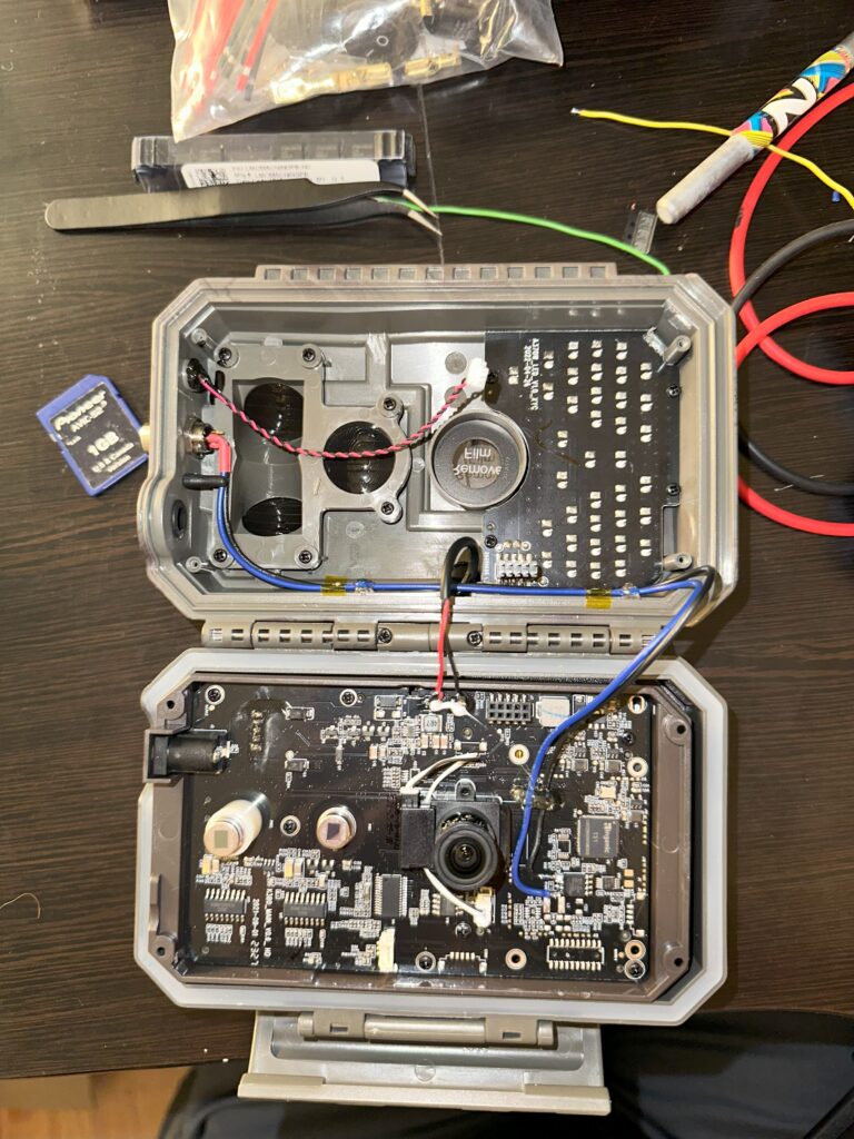
I soldered two wires to the GND and CS pins of the CMOS flash memory IC back to an M8 bulkhead connector. I used this connector style because I’ve become quite familiar with them working in the industrial automation space. They are very robust, but more importantly, waterproof.
Prototyping – Adafruit Feather M0
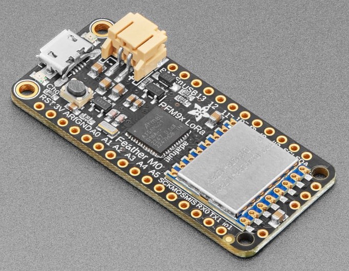
At this point, the proof of concept was completed, so I started to source components. After realizing the new revision Pro RF boards had been on backorder for a while, I decided to find a new board to work with which offered similar specs. I landed on the Adafruit Feather M0 which was about the same price and was smaller in footprint than the Sparkfun Pro RF.
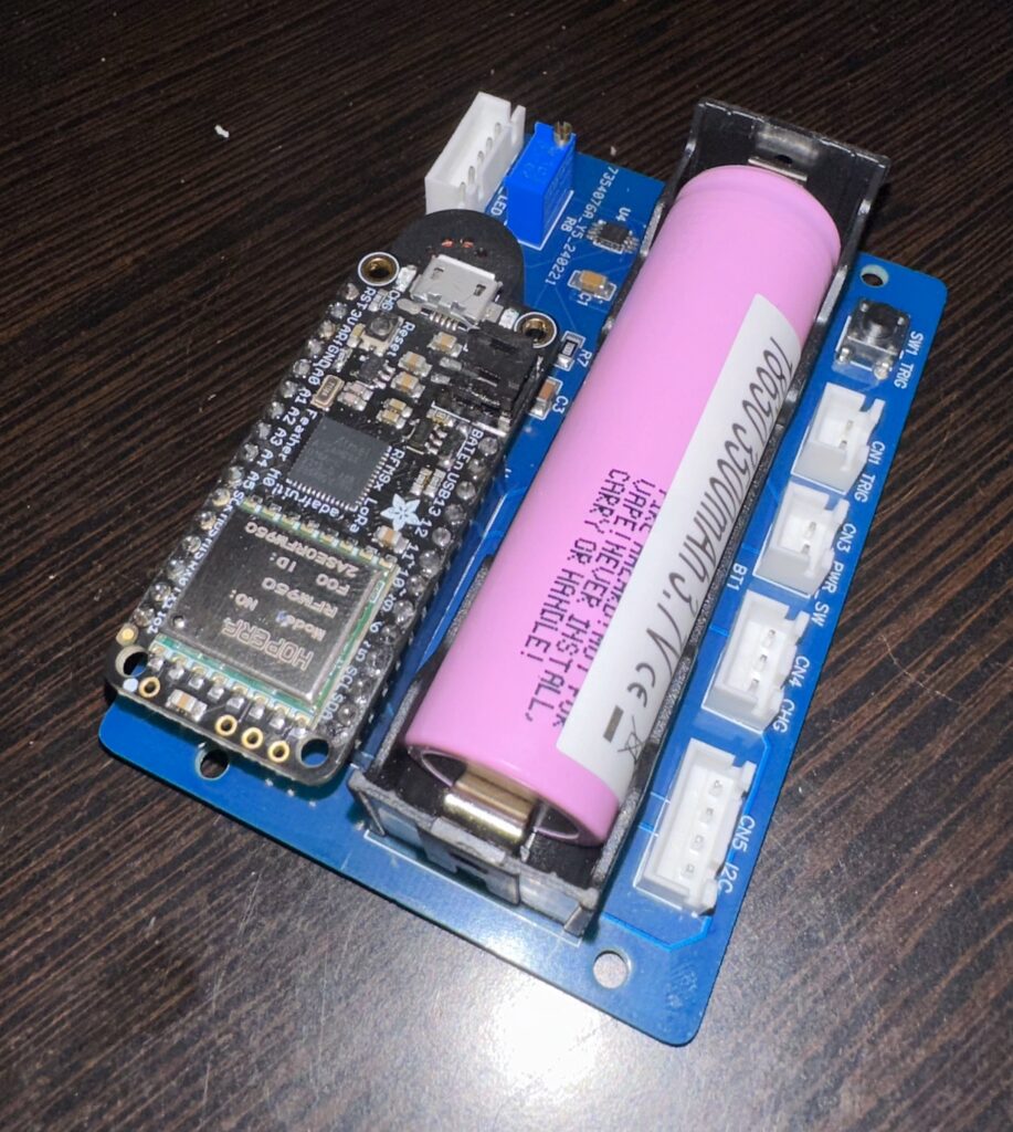
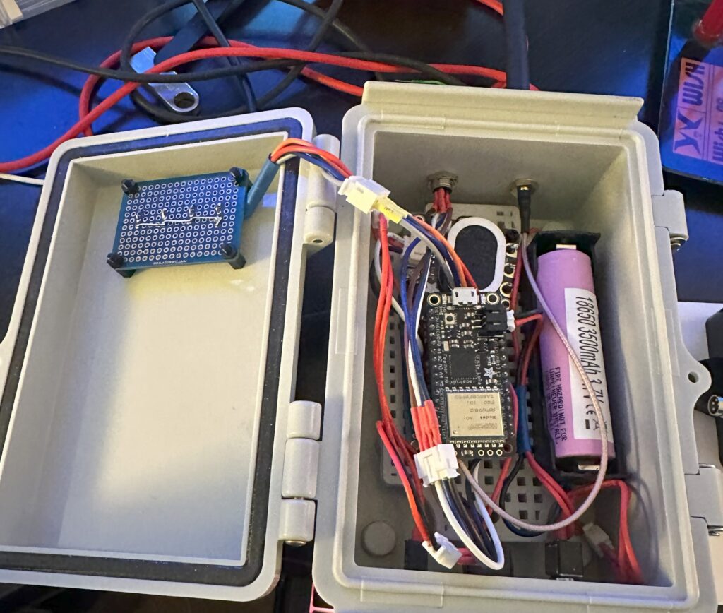
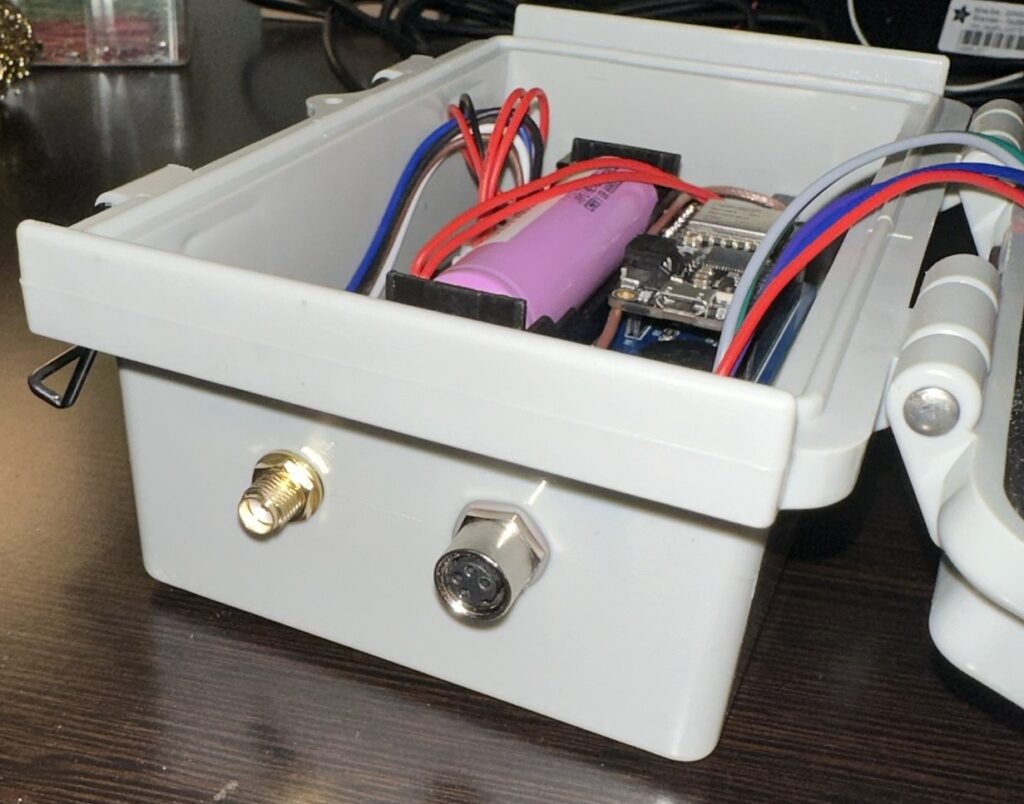
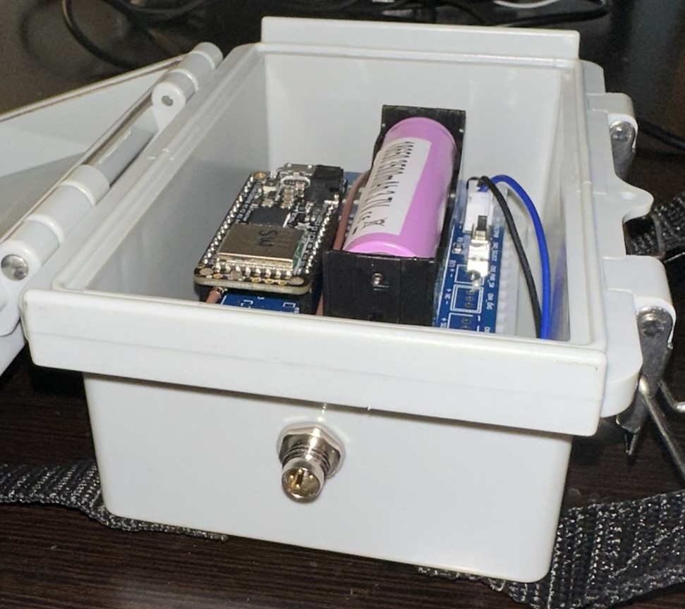
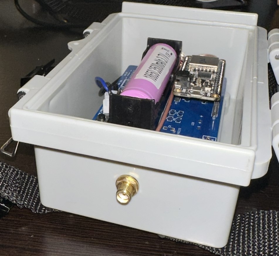
After deciding on a board, I started to laying out the circuit schematic and then built a prototype of the receiver and transmitter. Below is a picture of the prototype layout in a waterproof enclosure.
Receiver Code (v1.0)
The initial code I wrote for the receiver unit utilized timers to determine when to turn on and off the LED indicators. This code worked well for the first iteration.
// Adafruit Feather M0
// Wireless Deer Notification Receiver v1.0

#define DEBUG 0

#include <SPI.h>
#include <RH_RF95.h>
#include <string.h>
#include <NoDelay.h>
#include <Adafruit_PCF8574.h>
#include "I2CScanner.h"

// Feather M0 w/Radio
#define RFM95_CS    8
#define RFM95_INT   3
#define RFM95_RST   4

#if DEBUG
  #define debug_begin(...)  Serial.begin(__VA_ARGS__);
  #define debug(...)        Serial.print(__VA_ARGS__);
  #define debugln(...)      Serial.println(__VA_ARGS__);
#else
  #define debug_begin(...)
  #define debug(...)
  #define debugln(...)
#endif

// Change to 434.0 or other frequency, must match RX's freq!
#define RF95_FREQ 915.0

// Singleton instance of the radio driver
RH_RF95 rf95(RFM95_CS, RFM95_INT);

// Instance of I2C object
Adafruit_PCF8574 pcf;

I2CScanner scanner;
bool connected = false;

int StatusLED = 13; //Status LED on pin 13

int packetCounter = 0; //Counts the number of packets sent
long timeSinceLastPacket = 0; //Tracks the time stamp of last packet received

class Location
{
  public:
    String name;
    byte light_pin;
    byte i2c_add;
    noDelay timer;

    Location(String n, byte p, byte a, noDelay t)
    {
      name = n;
      light_pin = p;
      i2c_add = a;
      timer = t;
    };
};

// // LED pin numbers
// const byte pinLight1 = 6;
// const byte pinLight2 = 10;
// const byte pinLight3 = 11;
// const byte pinLight4 = 12;
// LED pin numbers
const byte pinLight1 = A1;
const byte pinLight2 = A2;
const byte pinLight3 = A3;
const byte pinLight4 = A4;

// I2C addresses
const byte i2c_add1 = 0x20;
const byte i2c_add2 = 0x21;
const byte i2c_add3 = 0x22;
const byte i2c_add4 = 0x23;

// Speaker output pin
const byte SPEAKER = A0;

const byte SPEAKER_ENABLE_PIN = 5;       //Trigger pin D5

// Strings to hold locations
static String location1 = "Northeast";
static String location2 = "Northwest";
static String location3 = "Southeast";
static String location4 = "Southwest";

// How long to keep LEDs on for after activity was detected
int ledOnTime = 10000;

// Strings for message and location
static String msg = "";
static String location = "";

char deviceLoc[20];

// Variable to hold location of first closing carret
int firstClosingCarret = 0;

// Setup timer to turn off LED1 after a certain amount of time
void turnOffLed1();
Location loc1 = Location(location1, pinLight1, i2c_add1, noDelay(ledOnTime, turnOffLed1, false));

// Setup timer to turn off LED2 after a certain amount of time
void turnOffLed2();
Location loc2 = Location(location2, pinLight2, i2c_add2, noDelay(ledOnTime, turnOffLed2, false));

// Setup timer to turn off LED3 after a certain amount of time
void turnOffLed3();
Location loc3 = Location(location3, pinLight3, i2c_add3, noDelay(ledOnTime, turnOffLed3, false));

// Setup timer to turn off LED4 after a certain amount of time
void turnOffLed4();
Location loc4 = Location(location4, pinLight4, i2c_add4, noDelay(ledOnTime, turnOffLed4, false));


// Setup
void setup()
{
  debugln("Starting setup.");
  pinMode(StatusLED, OUTPUT);
  pinMode(loc1.light_pin, OUTPUT);
  pinMode(loc2.light_pin, OUTPUT);
  pinMode(loc3.light_pin, OUTPUT);
  pinMode(loc4.light_pin, OUTPUT);

  pinMode(SPEAKER_ENABLE_PIN, INPUT_PULLDOWN);
  pinMode(SPEAKER, OUTPUT);

  debug_begin(9600);
  if (DEBUG == 1)
  {
    // It may be difficult to read serial messages on startup. The following
    // line will wait for serial to be ready before continuing. Comment out if not needed.
    while(!Serial) delay(1);
    delay(100);
  }

  debugln("RFM Server!");

  // Manual reset
  digitalWrite(RFM95_RST, LOW);
  delay(10);
  digitalWrite(RFM95_RST, HIGH);
  delay(10);

  //Initialize the Radio.
  while (!rf95.init()) {
    debugln("LoRa radio init failed");
    debugln("Uncomment '#define SERIAL_DEBUG' in RH_RF95.cpp for detailed debug info");
    while (1);
  }
  debugln("LoRa radio init OK!");

  // Defaults after init are 434.0MHz, modulation GFSK_Rb250Fd250, +13dbM
  if (!rf95.setFrequency(RF95_FREQ)) {
    debugln("setFrequency failed");
    while (1);
  }

  digitalWrite(StatusLED, LOW); //Turn off status LED

  scanner.Init();
  debugln("Finished with setup.");

 // The default transmitter power is 13dBm, using PA_BOOST.
 // If you are using RFM95/96/97/98 modules which uses the PA_BOOST transmitter pin, then
 // you can set transmitter powers from 5 to 23 dBm:
 // rf95.setTxPower(14, false);
}

// Loop
void loop()
{

  // Check if set time has past and if so, will run set function
  loc1.timer.update();
  loc2.timer.update();
  loc3.timer.update();
  loc4.timer.update();

  if (rf95.available()){
    // Should be a message for us now
    uint8_t buf[RH_RF95_MAX_MESSAGE_LEN];
    uint8_t len = sizeof(buf);

    if (rf95.recv(buf, &len)){
      digitalWrite(StatusLED, HIGH); //Turn on status LED
      timeSinceLastPacket = millis(); //Timestamp this packet

      msg = (char*)buf;
      firstClosingCarret = msg.indexOf('>');
      location = msg.substring(1, firstClosingCarret);

      if (location == location1){
        handleActivity(&loc1);
      }
      else if (location == location2){
        handleActivity(&loc2);
      }
      else if (location == location3){
        handleActivity(&loc3);
      }
      else if (location == location4){
        handleActivity(&loc4);
      }

      debug("Got message: ");
      debug((char*)buf);
      debug(rf95.headerId(), DEC);
      //SerialUSB.print(" RSSI: ");
      //SerialUSB.print(rf95.lastRssi(), DEC);
      debugln();
    }
    else
      debugln("Recieve failed");
  }

  else
  {
    // debugln("Radio not available");
  }

  //Turn off status LED if we haven't received a packet after 1s
  if(millis() - timeSinceLastPacket > 1000){
    digitalWrite(StatusLED, LOW); //Turn off status LED
    timeSinceLastPacket = millis(); //Don't write LED but every 1s
  }
}

// Function to turn off LED1
void turnOffLed1()
{
  // Set pin low
  digitalWrite(loc1.light_pin, LOW);
  setI2CPin(loc1.i2c_add, 0, LOW);
  debugln("Turned off LED1");
  // Stop the timer
  loc1.timer.stop();
}

// Function to turn off LED2
void turnOffLed2()
{
  // Set pin low
  digitalWrite(loc2.light_pin, LOW);
  setI2CPin(loc2.i2c_add, 0, LOW);
  debugln("Turned off LED2");
  // Stop the timer
  loc2.timer.stop();
}

// Function to turn off LED3
void turnOffLed3()
{
  // Set pin low
  digitalWrite(loc3.light_pin, LOW);
  setI2CPin(loc3.i2c_add, 0, LOW);
  debugln("Turned off LED3");
  // Stop the timer
  loc3.timer.stop();
}

// Function to turn off LED4
void turnOffLed4()
{
  // Set pin low
  digitalWrite(loc4.light_pin, LOW);
  setI2CPin(loc4.i2c_add, 0, LOW);
  debugln("Turned off LED4");
  // Stop the timer
  loc4.timer.stop();
}

void chirp() {  // Bird chirp
  // Only output sound if speaker enable pin is pulled low
  if (digitalRead(SPEAKER_ENABLE_PIN) == HIGH)
  {
    debugln("Chirped!");
    for(uint8_t i=180; i>160; i--)
      playTone(i,3);
    delay(100);
    for(uint8_t i=180; i>160; i--)
      playTone(i,3);
  }
  else
  {
    debugln("Speaker not enabled. No chirp.")
  }

}

void playTone(uint16_t tone1, uint16_t duration) {
  if(tone1 < 50 || tone1 > 15000) return;  // these do not play on a piezo
  for (long i = 0; i < duration * 1000L; i += tone1 * 2) {
    digitalWrite(SPEAKER, HIGH);
    delayMicroseconds(tone1);
    digitalWrite(SPEAKER, LOW);
    delayMicroseconds(tone1);
  }
}

void handleActivity(Location *loc)
{
  // Momentarily write pin low to indicate more activity if the light is already on
  debugln("Handling activity.");
  digitalWrite((*loc).light_pin, LOW);
  debugln("Wrote pin.");
  setI2CPin((*loc).i2c_add, 0, LOW);
  debugln("Wrote I2C.");

  // Delay
  delay(100);

  // Write high
  digitalWrite((*loc).light_pin, HIGH);
  setI2CPin((*loc).i2c_add, 0, HIGH);

  // Chirp sound
  chirp();
  // Set timer
  (*loc).timer.start();
}


  // Parse the values from the string
  sscanf(input, "<%s>: VBATT=%.2fV", &device, &voltage);

void setI2CPin(uint8_t address, uint8_t module_pin, bool val)
{
  // If address is accessible, write to it. If not, output debug message.
  // if (!pcf.begin(address, &Wire)) {
  //   debugln("Couldn't find PCF8574");
  // }
  connected = scanner.Check(address);

  if (connected)
  {
    debugln("I2C device connected.");
    pcf.begin(address, &Wire);
    pcf.pinMode(module_pin, OUTPUT);
    debugln("Sending I2C");
    pcf.digitalWrite(module_pin, !val);
  }
  else
  {
    debugln("I2C device not detected.")
  }
}
Transmitter Code (v1.0)
// Adafruit Feather M0
// Wireless Deer Notification Transmitter v1.0

#include <SPI.h>
#include <RH_RF95.h>
#include "ArduinoLowPower.h"

// Feather M0 w/Radio
#define RFM95_CS    8
#define RFM95_INT   3
#define RFM95_RST   4

// Change to 434.0 or other frequency, must match RX's freq!
#define RF95_FREQ 915.0


const int LED = 13;               //Status LED is on pin 13
const byte TRIGGER_PIN = 5;       //Trigger pin D5

uint8_t sendMessageFlag;            //Holds the state for sending message
const uint32_t oneShotTime = 3000;  //One-Shot time to reject double-triggers

char deviceID1[] = "<Southwest>"; //Device location
char msg1[100] = "";
uint8_t headerID = 0;

// Singleton instance of the radio driver
RH_RF95 rf95(RFM95_CS, RFM95_INT);

void setup() {
  // Setup status LED
  pinMode(LED, OUTPUT);
  // Setup trigger pin
  pinMode(TRIGGER_PIN, INPUT_PULLDOWN);
  // Initialize sendMessageFlag to 1, so we don't miss the first trigger
  sendMessageFlag = 1;

  // Initialize the Radio.
  if (rf95.init() == false)
  {
    // SerialUSB.println("Radio Init Failed - Freezing");
    while (1);
  }
  else
  {
    // An LED inidicator to let us know radio initialization has completed.
    // SerialUSB.println("Transmitter up!");
    digitalWrite(LED, HIGH);
    delay(500);
    digitalWrite(LED, LOW);
    delay(500);
  }

  // Set frequency
  rf95.setFrequency(RF95_FREQ);

   // The default transmitter power is 13dBm, using PA_BOOST.
   // If you are using RFM95/96/97/98 modules which uses the PA_BOOST transmitter pin, then
   // you can set transmitter powers from 5 to 23 dBm:
   // Transmitter power can range from 14-20dbm.
   rf95.setTxPower(20, false);
  //  rf95.setHeaderFrom(*(uint8_t*)deviceID);

  // Attach interrupt to trigger pin
  LowPower.attachInterruptWakeup(TRIGGER_PIN, onInterrupt, RISING);
  // Delay before going to sleep
  delay(5000);
  // Go to sleep
  GoToSleep();
}

// Main loop
void loop()
{
  // If sendMessageFlag is set
  if(sendMessageFlag == 1)
  {
    // Send message
    sendMessage();
    // Delay
    delay(oneShotTime);
    // Go to sleep
    GoToSleep();
  }
}

// Send message method
void sendMessage()
{
  // SerialUSB.println("Sending message");
  // Set radio in TX mode (not sure if this is 100% necessary)
  rf95.setModeTx();
  // delay(1000);
  //Format message
  // char str[] = "Hi there!";
  msg1[0] = (char)0;
  strcat(msg1, deviceID1);
  // strcat(msg1, str);

  // Set header ID
  rf95.setHeaderId(headerID);
  // Turn on status LED
  digitalWrite(LED, HIGH);
  // Send the message
  rf95.send((uint8_t*)msg1, sizeof(msg1));
  // Wait for message to finish sending
  rf95.waitPacketSent();
  // Turn off status LED
  digitalWrite(LED, LOW);
  // Increment header ID
  headerID++;
}

// Go to sleep method
void GoToSleep()
{
  // Set the flag low
  sendMessageFlag = 0;
  // Put radio to sleep
  rf95.sleep();
  // Put processor to sleep
  LowPower.deepSleep();
}

// Interrupt callback
void onInterrupt()
{
  // If the send message flag hasn't been set, set it
  if(sendMessageFlag == 0)
    sendMessageFlag = 1;
}
Custom PCB Design
After building the receiver prototype, I quickly realized that I did not want to use perf board to make all these units. The amount of time it took me to solder up everything for one board was about 8 hours. At that point, I knew I wanted professionally made PCBs that I could use SMD and thru hole components on. I had never done this before, but have worked on my share of circuit boards, so I already had a good idea of how they are typically laid out. I had seen some ads for JLCPCB on a YouTube channel I watch, so I figured I’d start there. From there, I found a software called EasyEDA which allows for circuit schematic layout and PCB layout. I downloaded the software and started layout out my schematic.
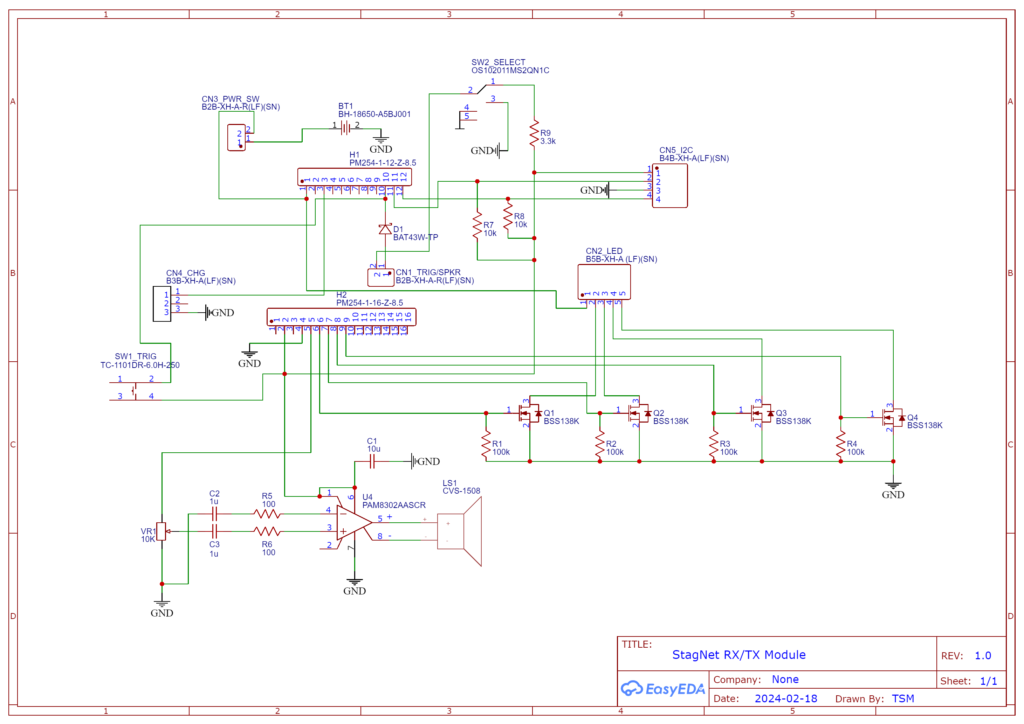
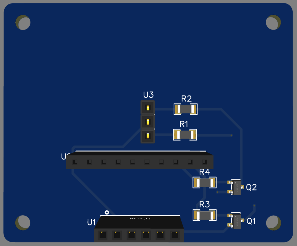
After layout out the circuit schematic, I then started layout out the traces for the PCB. I went through a few iterations of PCB layout. A few had some design flaws, but the third and final one I ended up with can be seen below. To keep cost down, I designed the board such that I could populate it as a receiver board or a transmitter board. Most of the pads for the transmitter board are unused.
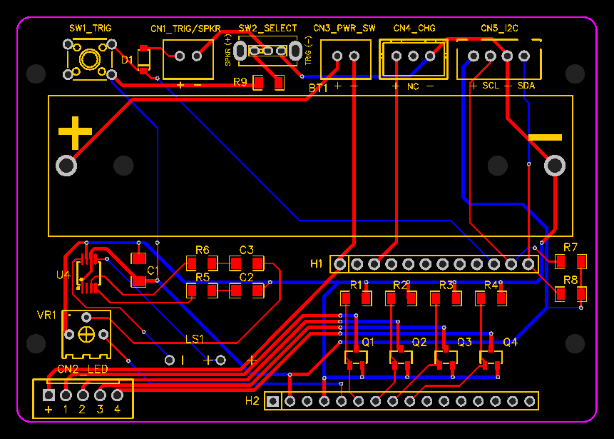
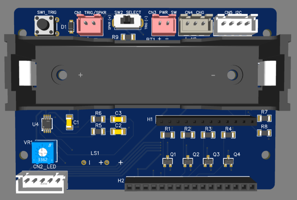
Some really nice features to the EasyEDA were that it has built-in libraries of parts and also has parts that have been added by the community. On top of that, it also allows you to see a 3D rendering of the PCB with all the components on it which I found to be really helpful to understand potential spacing constraint issues..
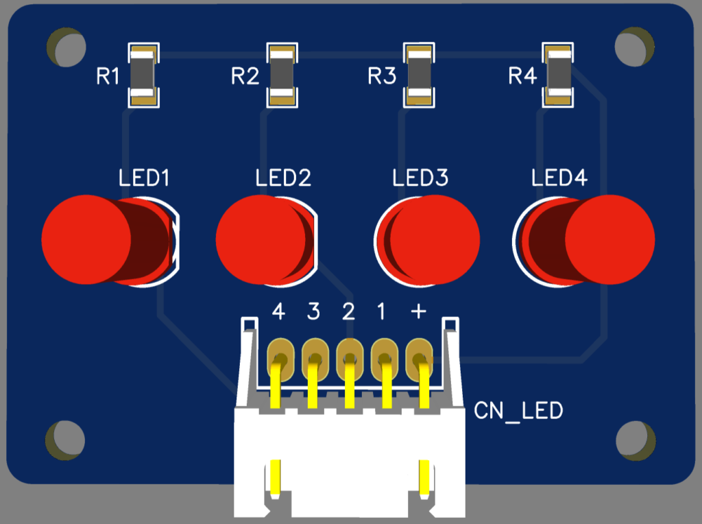
I ended up designing another PCB for the LED indicators too.
Build
After receiving the PCBs about a week later, I was then able to solder up all the components and put it into a waterproof enclosure. Below is a picture of the receiver board with the LED indicator board.
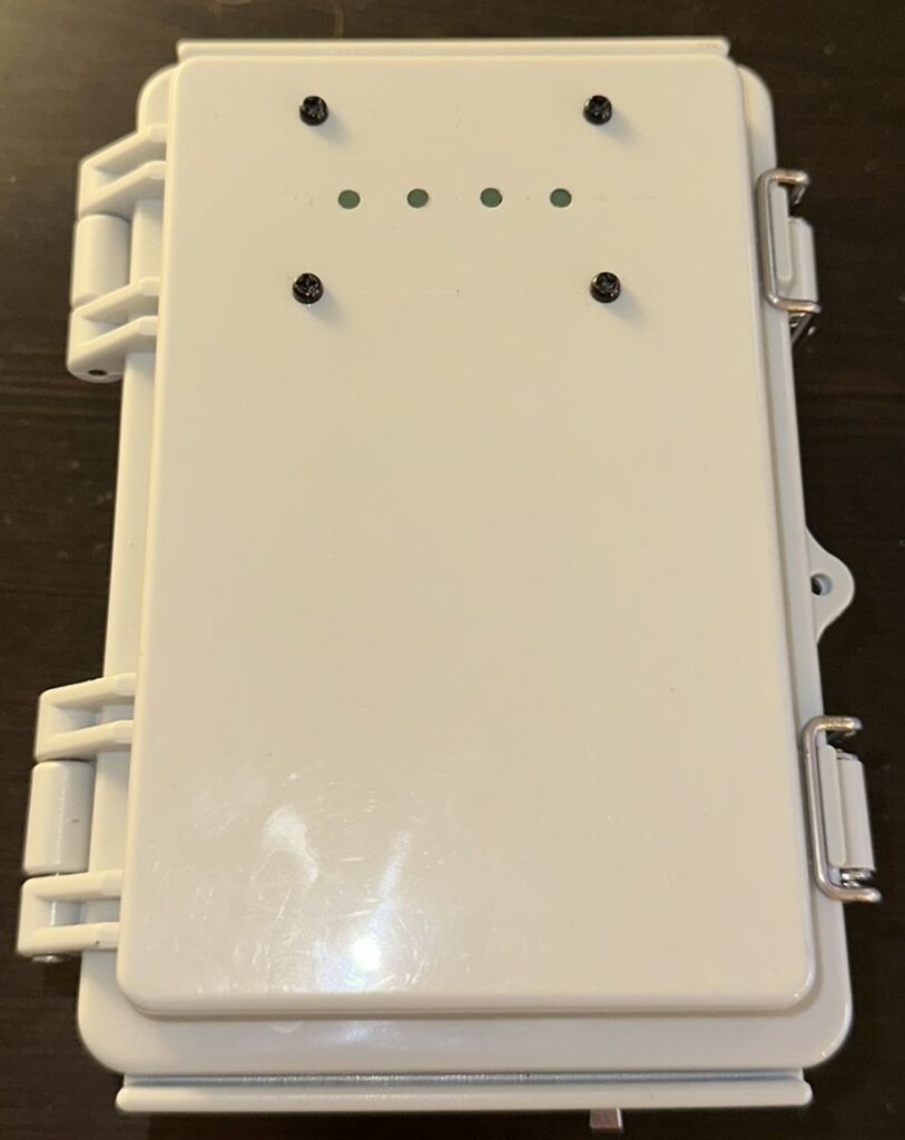
A picture of the receiver unit closed up, showing the LED indicator lights.
On the bottom left is a switch to turn on/off the speaker and on the bottom right is the main power switch. In the middle of the two switches is a USB-C port for charging the battery. Unlike the transmitters which draw very little current due to being in deep sleep most of the time, the receiver must always be listening for messages and thus draws much more current (~120mA) on average. With this battery, that would only last me about 29 hours, so I put the USB-C port in there so I could charge the battery while sitting in my deer blind with a battery bank.
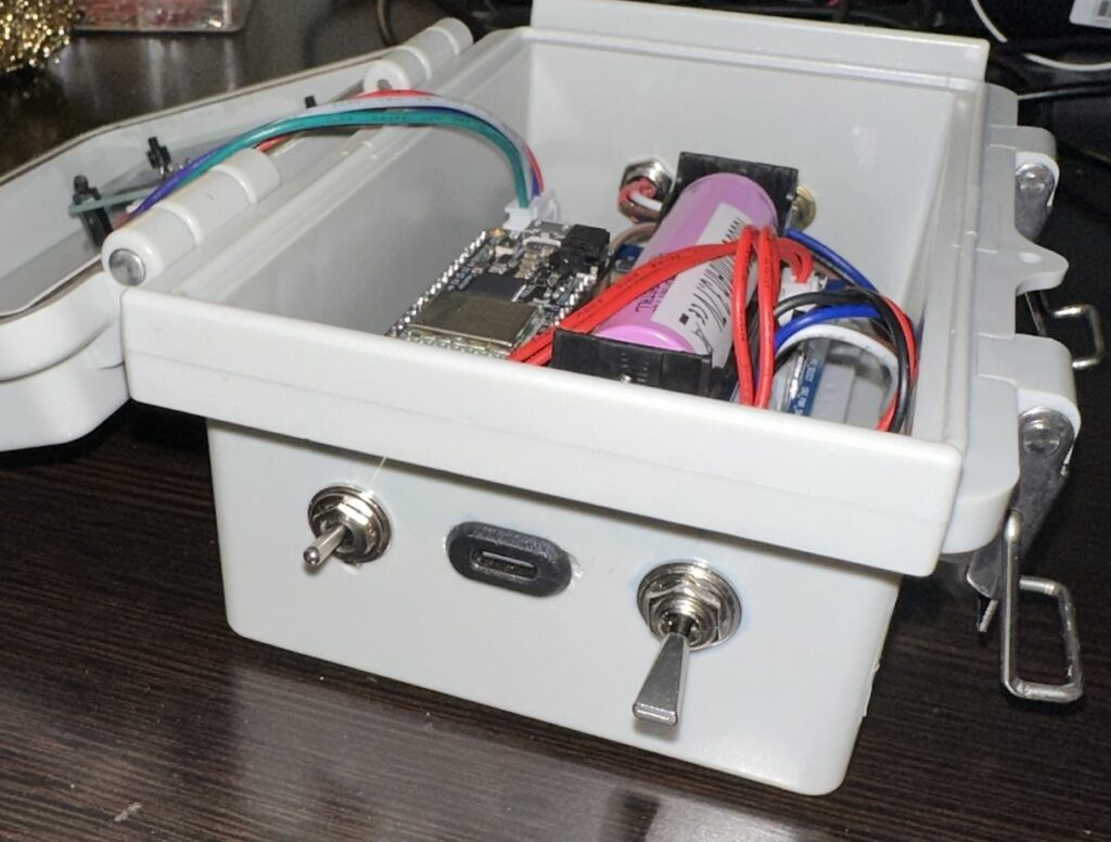
On the top right is an M8 connector which serves as the remote I/O port and utilizes I2C comms. At the top left is an SMA connector for the antenna.
The next step was to design the remote LEDs. I wanted to use the same M8 4-pin bulkhead connectors, so I knew I needed to get the number of pins down to 4. Having 4 remote LED indicators, I decided to use the I2C protocol to remotely control 4 I2C GPIO expanders. Using I2C would also allow me to expand the number of transmitters beyond 4 if I ever wanted to do so in the future.
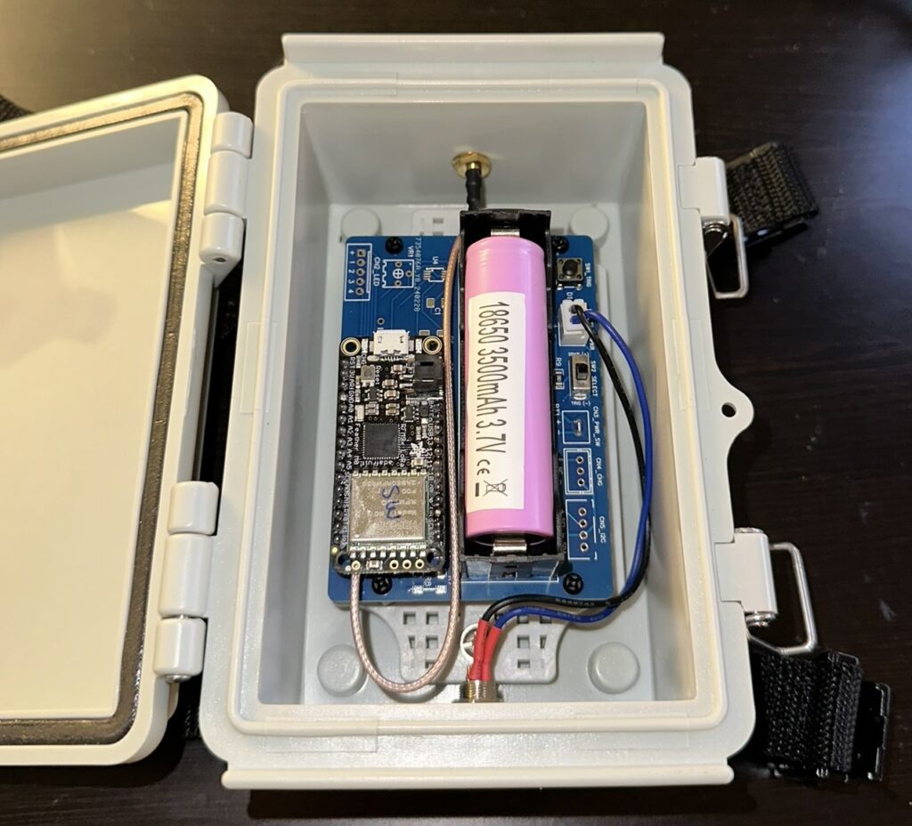
A picture of a remote I/O LED indicator.
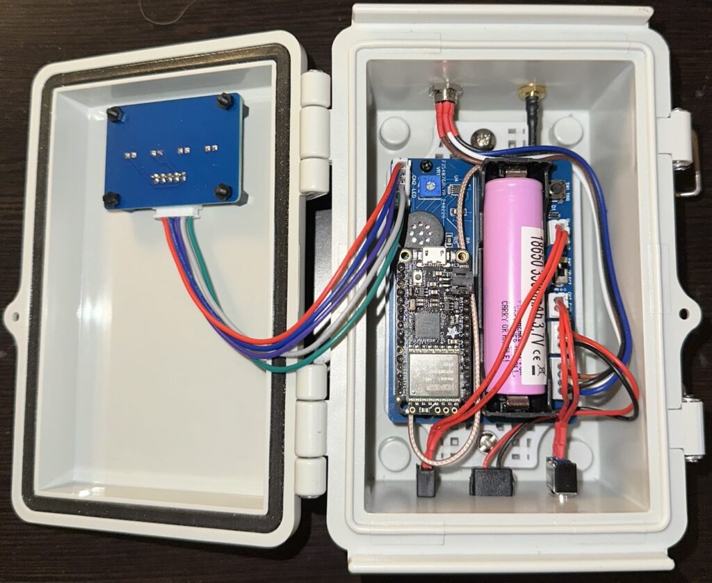
A picture of the inside of a remote I/O unit.
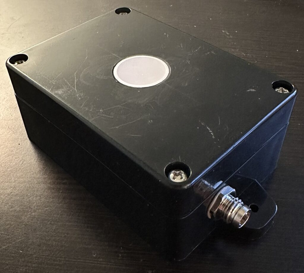
For the transmitter units, I decided to utilize the same PCB as the receiver to reduce cost and simplicity.
On the bottom of the transmitter unit is an M8 connector to receive the trigger signal from the camera.
On the top of the transmitter unit is an SMA connector for the antenna.
Receiver Code (v2.0)
After testing out the v1.0 code at home, and then installing the devices around my blind at camp, I decided it would be nice to have feedback from the transmitters when their battery voltage was below a certain threshold. Only having 4 LED indicators and a speaker to work with and working around the current functionality, I quickly realized that my v1.0 code was going to be very difficult to modify in order to get the feedback I wanted. I did not want to use the speaker for low battery indication because the speaker isn’t always enabled. This was by design so that I could turn off the audio feedback if I wanted to. The only other option was to use the 4 LED indicators which turn on for 10 seconds when activity is sensed for a given location.
I decided that a blink of the LED at the end of the 10 second on-time would be a good way to have decent indication of low battery without disturbing the existing functionality too much. To do this, I chose to use a state machine code design over the timer-based code in v1.0.
// Adafruit Feather M0
// Wireless Deer Notification Receiver v2.0

// Enable or disable debugging mode
#define DEBUG 0

// Include the necessary libraries for functionality
#include <SPI.h>                   // Library for SPI communication with the LoRa module
#include <RH_RF95.h>               // RadioHead library for LoRa communication
#include <string.h>                // Standard library for string operations
#include <NoDelay.h>               // Library for non-blocking delay functionality
#include <Adafruit_PCF8574.h>      // Library for using the I2C IO expander PCF8574
#include "I2CScanner.h"            // Custom utility to scan for connected I2C devices

// Define pin assignments for the Feather M0 LoRa board
#define RFM95_CS    8              // Chip select pin for the LoRa module
#define RFM95_INT   3              // Interrupt pin for the LoRa module
#define RFM95_RST   4              // Reset pin for the LoRa module

// Debugging macros: Define how to handle debugging based on the DEBUG flag
#if DEBUG
  #define debug_begin(...)  Serial.begin(__VA_ARGS__)     // Initialize serial communication for debugging
  #define debug(...)        Serial.print(__VA_ARGS__)     // Print debug messages
  #define debugln(...)      Serial.println(__VA_ARGS__)   // Print debug messages with a newline
#else
  #define debug_begin(...)  // Do nothing if debugging is disabled
  #define debug(...)        // Do nothing if debugging is disabled
  #define debugln(...)      // Do nothing if debugging is disabled
#endif

// Set the operating frequency for the LoRa radio (must match the transmitter's frequency)
#define RF95_FREQ 915.0             // Frequency in MHz

// Create a singleton instance of the RH_RF95 driver
RH_RF95 rf95(RFM95_CS, RFM95_INT);  // Arguments: chip select pin and interrupt pin

// Create an instance of the I2C expander object for additional I/O control
Adafruit_PCF8574 pcf;

// Create an instance of the I2C scanner utility
I2CScanner scanner;

// Define possible states for each location
enum State { OFF, ON, TRIGGER_BLINK, BLINKING_OFF };

// Flag to indicate if the I2C device is connected
bool connected = false;

// Pin definition for the status LED
int StatusLED = 13;                 // Status LED on pin 13

// Variable for keeping time since last packet was received
unsigned long timeSinceLastPacket = 0; // Timestamp of the last packet received

const unsigned long t_On = 10000;          // Time in milliseconds for LED to stay on
const unsigned long blinkDuration = 100;   // Duration for blink on retrigger
const unsigned long preOffBlinkTime = 150; // Time before t_On to start pre-off blink. preOffBlinkTime should be 1.5-2 times larger than blinkDuration
const float lowBatteryThreshold = 3.6;     // Voltage threshold for low battery

// Speaker output pin
const byte SPEAKER = A0;

const byte SPEAKER_ENABLE_PIN = 5;       //Trigger pin D5

// Variable to store where the current message came from
char msg_loc[10];

// Variable to store voltage from transmitter of current message
float msg_voltage;


// Function to set the state of a pin on an I2C device
void setI2CPin(uint8_t address, uint8_t module_pin, bool val){
  // Check if the I2C device at the given address is connected
  connected = scanner.Check(address);

  // If the I2C device is connected, proceed to configure and control the pin
  if (connected){
    // Initialize the PCF8574 I2C expander at the specified address using the Wire library
    pcf.begin(address, &Wire);

    // Set the specified pin on the I2C expander as an output pin
    pcf.pinMode(module_pin, OUTPUT);

    // Write the desired value to the pin
    // Note: The value is inverted (!val) because the expander uses active-low logic
    pcf.digitalWrite(module_pin, !val);
  }
  else {
    // If the I2C device is not detected, print an error message
    debugln("I2C device not detected.");
  }
}


// Function to generate a "bird chirp" sound effect
void chirp() {
  // Only output sound if the speaker enable pin is pulled high
  if (digitalRead(SPEAKER_ENABLE_PIN) == HIGH) {
    debugln("Chirped!");  // Output a debug message indicating that the chirp sound is being played

    // Loop to generate a series of tones, starting from frequency 180 and decreasing to 160
    for (uint8_t i = 180; i > 160; i--) {
      playTone(i, 3);  // Play a tone at frequency 'i' for 3 milliseconds
    }

    delay(100);  // Short pause between the two chirps

    // Repeat the tone series to complete the "chirp" effect
    for (uint8_t i = 180; i > 160; i--) {
      playTone(i, 3);  // Play a tone at frequency 'i' for 3 milliseconds
    }
  }
  else {
    debugln("Speaker not enabled. No chirp.");  // Output a debug message if the speaker is not enabled
  }
}


// Function to play a tone on a speaker
// Parameters:
// - tone1: The frequency of the tone in microseconds
// - duration: The duration for which to play the tone, in milliseconds
void playTone(uint16_t tone1, uint16_t duration) {
  // Check if the tone frequency is within a valid range for a piezo speaker
  if (tone1 < 50 || tone1 > 15000) return;  // If the frequency is too low or too high, exit the function

  // Loop to generate the tone for the specified duration
  for (long i = 0; i < duration * 1000L; i += tone1 * 2) {
    digitalWrite(SPEAKER, HIGH);            // Set the speaker pin high to create sound
    delayMicroseconds(tone1);               // Wait for the specified tone frequency in microseconds
    digitalWrite(SPEAKER, LOW);             // Set the speaker pin low to stop the sound
    delayMicroseconds(tone1);               // Wait again for the specified tone frequency
  }
}


// Struct to represent a location with associated LED, I2C, and state information
struct Location {
    byte ledPin;                  // The pin number for the LED associated with this location
    byte i2cAddress;              // The I2C address of the external device (e.g., I/O expander)
    float voltage;                // Voltage level, used to determine low battery status
    const char* locationID;       // A string identifier for the location (e.g., "Location A")
    State state;                  // Current state of the LED (e.g., ON, OFF, BLINKING)
    unsigned long previousMillis; // Stores the time when the LED state was last changed
    unsigned long blinkStartTime; // Time when a temporary blink started
    bool preOffBlinkDone;         // Flag to ensure the pre-off blink occurs only once

    // Method to handle LED state updates based on elapsed time and voltage level
    void updateState() {
        unsigned long currentMillis = millis(); // Get the current time

        // Use a switch statement to handle different LED states
        switch (state) {
            case TRIGGER_BLINK:
                // If the initial blink duration has passed, turn the LED on and switch to ON state
                if (currentMillis - blinkStartTime >= blinkDuration) {
                    state = ON;                                // Change state to ON
                    digitalWrite(ledPin, HIGH);                // Turn the LED on
                    setI2CPin(i2cAddress, 0, true);            // Set the I2C pin to active
                    previousMillis = millis();                 // Record the time the LED was turned on
                    debugln("Transition to ON after initial blink.");
                }
                break;

            case ON:
                // If the voltage is low and pre-off blink hasn't been done, start a pre-off blink
                if (!preOffBlinkDone && voltage < lowBatteryThreshold &&
                    currentMillis - previousMillis >= t_On - preOffBlinkTime) {
                    state = BLINKING_OFF;                      // Change state to BLINKING_OFF
                    blinkStartTime = currentMillis;            // Record the start time of the blink
                    digitalWrite(ledPin, LOW);                 // Blink the LED off
                    preOffBlinkDone = true;                    // Mark that the pre-off blink is done
                    setI2CPin(i2cAddress, 0, false);           // Set the I2C pin to inactive
                    debugln("Entering BLINKING_OFF due to low battery.");
                }
                // If the LED has been on for `t_On` duration, turn it off and transition to OFF state
                else if (currentMillis - previousMillis >= t_On) {
                    state = OFF;                               // Change state to OFF
                    digitalWrite(ledPin, LOW);                 // Turn the LED off
                    setI2CPin(i2cAddress, 0, false);           // Set the I2C pin to inactive
                    debugln("Transition to OFF after t_On expires.");
                }
                break;

            case BLINKING_OFF:
                // If the blink duration has passed, turn the LED back on and switch to ON state
                if (currentMillis - blinkStartTime >= blinkDuration) {
                    state = ON;                                // Change state to ON
                    digitalWrite(ledPin, HIGH);                // Turn the LED back on
                    setI2CPin(i2cAddress, 0, true);            // Set the I2C pin to active
                    debugln("Returning to ON after low battery blink.");
                }
                break;

            case OFF:
                // Keep the LED off; no action is needed while in the OFF state
                break;
        }
    }

    // Method to trigger an initial blink on receiving a new message and reset the timer
    void trigger() {
        state = TRIGGER_BLINK;          // Set state to TRIGGER_BLINK to start a brief blink
        blinkStartTime = millis();      // Record the start time of the blink
        digitalWrite(ledPin, LOW);      // Turn the LED off briefly for the blink
        setI2CPin(i2cAddress, 0, false); // Set the I2C pin to inactive
        preOffBlinkDone = false;        // Reset the pre-off blink flag
        debug("Triggering LED for ");   // Debug message indicating which location is being triggered
        debugln(locationID);

        // Call an external function to play a chirp sound to indicate a new message
        chirp();
    }
};


// Array to hold all transmitter location objects
Location locations[] = {
    {A1, 0x20, 0.0, "Northeast", OFF, 0, 0, true},
    {A2, 0x21, 0.0, "Northwest", OFF, 0, 0, true},
    {A3, 0x22, 0.0, "Southeast", OFF, 0, 0, true},
    {A4, 0x23, 0.0, "Southwest", OFF, 0, 0, true}
};


// Setup
void setup() {
  debugln("Starting setup.");           // Print a debug message indicating the setup process has started
  pinMode(StatusLED, OUTPUT);           // Set the status LED pin as an output

  // Loop through each Location object in the locations array
  for (Location &loc : locations) {
    pinMode(loc.ledPin, OUTPUT);        // Set each location's LED pin as an output
    digitalWrite(loc.ledPin, LOW);      // Ensure all LEDs are turned off
    setI2CPin(loc.i2cAddress, 0, false); // Set the I2C pin to inactive for each location
  }

  pinMode(SPEAKER_ENABLE_PIN, INPUT_PULLDOWN); // Set the speaker enable pin as an input with pull-down resistor
  pinMode(SPEAKER, OUTPUT);                    // Set the speaker pin as an output

  debug_begin(9600);               // Initialize serial communication for debugging at 9600 baud rate
  if (DEBUG == 1) {                // If debugging is enabled
    // Wait for the serial port to be ready before continuing
    // This is useful when monitoring serial messages at startup
    while (!Serial) delay(1);      // Wait until the Serial port is ready
    delay(100);                    // Short delay to stabilize serial communication
  }

  debugln("RFM Server!");          // Print a message indicating the RFM server initialization

  // Perform a manual reset of the LoRa module
  digitalWrite(RFM95_RST, LOW);    // Pull the reset pin low to reset the module
  delay(10);                       // Wait for 10 milliseconds
  digitalWrite(RFM95_RST, HIGH);   // Pull the reset pin high to complete the reset
  delay(10);                       // Wait another 10 milliseconds for stabilization

  // Initialize the LoRa radio module
  while (!rf95.init()) {               // Attempt to initialize the radio
    debugln("LoRa radio init failed"); // Print an error message if initialization fails
    debugln("Uncomment '#define SERIAL_DEBUG' in RH_RF95.cpp for detailed debug info"); // Suggest enabling detailed debug info if necessary
    while (1);                         // Halt the program indefinitely if initialization fails
  }
  debugln("LoRa radio init OK!");      // Print a success message if initialization is successful

  // Set the frequency for the LoRa radio
  if (!rf95.setFrequency(RF95_FREQ)) {  // Attempt to set the radio frequency
    debugln("setFrequency failed");     // Print an error message if frequency setup fails
    while (1);                          // Halt the program if frequency setup fails
  }

  // Turn off the status LED after setup
  digitalWrite(StatusLED, LOW);
  // Initialize the I2C scanner to detect connected I2C devices
  scanner.Init();
  debugln("Finished with setup."); // Print a debug message indicating setup completion
}

// Get locationID and update corresponding Location object in array
void receiveMessage(const char* locationID, float voltage) {
    for (Location &loc : locations) {
        if (strcmp(locationID, loc.locationID) == 0) {
            loc.voltage = voltage;         // Update voltage
            debug(loc.locationID);         // Show location and voltage
            debug(" V=");
            debugln(loc.voltage);
            loc.trigger();                 // Trigger LED, chirp, and I2C
        }
    }
}


// Main loop
void loop(){
  if (rf95.available()){
    // Should be a message for us now
    uint8_t buf[RH_RF95_MAX_MESSAGE_LEN];
    uint8_t len = sizeof(buf);

    // Receive the message
    if (rf95.recv(buf, &len)){
      digitalWrite(StatusLED, HIGH); //Turn on status LED
      timeSinceLastPacket = millis(); // Upate time since last packet was received

      // If items are parsed out correctly, this is likely a message from one of the transmitters
      if (parseData((char*)buf, msg_loc, &msg_voltage)){
        receiveMessage(msg_loc, msg_voltage); // Process received location and voltage
      }
    }

    else{
      debugln("Recieve failed");
    }
  }

  // Update state for each location based on timers
  for (Location &loc : locations) {
      loc.updateState();
  }

  //Turn off status LED if we haven't received a packet after 1s
  if(millis() - timeSinceLastPacket > 1000){
    digitalWrite(StatusLED, LOW); //Turn off status LED
    timeSinceLastPacket = millis(); //Don't write LED but every 1s
  }
}


// Function to parse message and get location and voltage from it.
bool parseData(const char *input, char *location, float *voltage) {
    // Temporary buffer for voltage as a string
    char voltageStr[10];

    // Locate the start and end of the location name using '<' and '>'
    char *startLoc = strchr(input, '<');
    char *endLoc = strchr(input, '>');
    if (!startLoc || !endLoc || endLoc <= startLoc) return false; // Early return if location markers are invalid

    // Copy and null-terminate the location name
    int locLength = endLoc - startLoc - 1;
    strncpy(location, startLoc + 1, locLength);
    location[locLength] = '\0';

    // Locate the start of the voltage value and the end 'V' character
    char *startVolt = strchr(input, '=');
    char *endVolt = strrchr(input, 'V');
    if (!startVolt || !endVolt || endVolt <= startVolt) return false; // Early return if voltage markers are invalid

    // Copy and null-terminate the voltage value
    int voltLength = endVolt - startVolt - 1;
    strncpy(voltageStr, startVolt + 1, voltLength);
    voltageStr[voltLength] = '\0';

    // Convert the voltage string to a float
    *voltage = atof(voltageStr);
    if (*voltage == 0.0 && strcmp(voltageStr, "0") != 0) return false; // Check if conversion failed

    // If both parsing steps are successful, return true
    return true;
}
Transmitter Code (v2.0)
// Adafruit Feather M0
// Wireless Deer Notification Transmitter v2.0

// Enable or disable debugging mode
#define DEBUG 0

// Debugging macros: Define how to handle debugging based on the DEBUG flag
#if DEBUG
  #define debug_begin(...)  Serial.begin(__VA_ARGS__)     // Initialize serial communication for debugging
  #define debug(...)        Serial.print(__VA_ARGS__)     // Print debug messages
  #define debugln(...)      Serial.println(__VA_ARGS__)   // Print debug messages with a newline
#else
  #define debug_begin(...)  // Do nothing if debugging is disabled
  #define debug(...)        // Do nothing if debugging is disabled
  #define debugln(...)      // Do nothing if debugging is disabled
#endif

#include <SPI.h>
#include <RH_RF95.h>
#include "ArduinoLowPower.h"
#include <stdint.h>
#include <stdio.h>

// Define pin assignments for the Feather M0 LoRa board
#define RFM95_CS    8              // Chip select pin for the LoRa module
#define RFM95_INT   3              // Interrupt pin for the LoRa module
#define RFM95_RST   4              // Reset pin for the LoRa module

// Battery voltage pin
#define VBAT_PIN A7
// Battery voltage variable
float measuredvbat;

// Set the operating frequency for the LoRa radio (must match the receiver's frequency)
#define RF95_FREQ 915.0

const int LED = 13;               // Status LED is on pin 13
const byte TRIGGER_PIN = 5;       // Trigger pin D5

uint8_t sendMessageFlag;            // Holds the state for sending message
const uint32_t oneShotTime = 3000;  // One-Shot time to reject double-triggers

char deviceID[] = "<Southwest>";  // Device location
char msg[100] = "";               // Variable to hold message
uint8_t headerID = 0;             // Message header ID

// Create a singleton instance of the RH_RF95 driver
RH_RF95 rf95(RFM95_CS, RFM95_INT);

// Setup
void setup() {

  debug_begin(9600);               // Initialize serial communication for debugging at 9600 baud rate
  if (DEBUG == 1) {                // If debugging is enabled
    // Wait for the serial port to be ready before continuing
    // This is useful when monitoring serial messages at startup
    while (!Serial) delay(1);      // Wait until the Serial port is ready
    delay(100);                    // Short delay to stabilize serial communication
  }

  debugln("RFM Client!");          // Print a message indicating the RFM client initialization

  // Setup status LED
  pinMode(LED, OUTPUT);
  // Setup trigger pin
  pinMode(TRIGGER_PIN, INPUT_PULLDOWN);
  pinMode(VBAT_PIN, INPUT);
  // Initialize sendMessageFlag to 1, so we don't miss the first trigger
  sendMessageFlag = 1;

  // Perform a manual reset of the LoRa module
  digitalWrite(RFM95_RST, LOW);    // Pull the reset pin low to reset the module
  delay(10);                       // Wait for 10 milliseconds
  digitalWrite(RFM95_RST, HIGH);   // Pull the reset pin high to complete the reset
  delay(10);                       // Wait another 10 milliseconds for stabilization

  // Initialize the Radio.
  if (rf95.init() == false){
    // SerialUSB.println("Radio Init Failed - Freezing");
    while (1);
  }

  else{
    // An LED inidicator to let us know radio initialization has completed.
    // SerialUSB.println("Transmitter up!");
    digitalWrite(LED, HIGH);
    delay(500);
    digitalWrite(LED, LOW);
    delay(500);
  }

  // Set frequency
  rf95.setFrequency(RF95_FREQ);

   // The default transmitter power is 13dBm, using PA_BOOST.
   // If you are using RFM95/96/97/98 modules which uses the PA_BOOST transmitter pin, then
   // you can set transmitter powers from 5 to 23 dBm:
   // Transmitter power can range from 14-20dbm.
   rf95.setTxPower(20, false);
  //  rf95.setHeaderFrom(*(uint8_t*)deviceID);

  // Attach interrupt to trigger pin
  LowPower.attachInterruptWakeup(TRIGGER_PIN, onInterrupt, RISING);

  if (DEBUG == 0){
    // Delay before going to sleep
    delay(5000);
    // Go to sleep
    GoToSleep();
  }
}

// Main loop
void loop(){
  // If sendMessageFlag is set
  if(sendMessageFlag == 1){
    // Send message
    sendMessage();
    // Delay
    delay(oneShotTime);
    // Go not debugging, go to sleep
    if (DEBUG == 0){
      GoToSleep();
    }
  }
}

// Send message method
void sendMessage()
{
  // SerialUSB.println("Sending message");
  // Set radio in TX mode (not sure if this is 100% necessary)
  rf95.setModeTx();
  // delay(1000);
  //Format message
  float batteryVoltage = getBatteryVoltage();

  // Get the message with the device ID and battery voltage
  char* message = createMessage(msg, deviceID, batteryVoltage);

  // Set header ID
  rf95.setHeaderId(headerID);
  // Turn on status LED
  digitalWrite(LED, HIGH);
  // Send the message

  debugln(message);
  uint8_t buff[strlen(message)+1];

  // Copy the data into destination
  memcpy(buff, (uint8_t*)message, strlen(message));
  buff[strlen(message)] = 0;

  rf95.send(buff, strlen(message)+1);
  // Wait for message to finish sending
  rf95.waitPacketSent();
  // Turn off status LED
  digitalWrite(LED, LOW);
  // Increment header ID
  headerID++;
}

// Enter deep sleep
void GoToSleep(){
  // Set the sendMessageFlag low
  sendMessageFlag = 0;
  // Put radio to sleep
  rf95.sleep();
  // Put processor to sleep
  LowPower.deepSleep();
}

// Calculate battery voltage
float getBatteryVoltage(){
  float battery_voltage = analogRead(VBAT_PIN); // Read voltage on battery voltage pin
  battery_voltage *= 2;    // We divided by 2, so multiply back
  battery_voltage *= 3.3;  // Multiply by 3.3V, our reference voltage
  battery_voltage /= 1024; // Convert to voltage
  return battery_voltage;
}

// Function to create a message with the device ID and battery voltage
// The buffer is passed as an argument, and the function returns the pointer to the buffer
char* createMessage(char* buffer, const char* deviceID, float voltage) {
  // Format the string into the provided buffer
  snprintf(buffer, sizeof(msg), "%s: VBATT=%.2fV", deviceID, voltage);

  // Return the buffer (which is a char array)
  return buffer;
}

// Interrupt callback for when a trigger occurs
void onInterrupt(){
  // If the send message flag hasn't been set, set it
  if(sendMessageFlag == 0)
    sendMessageFlag = 1;
}